4 Bit Odd Parity Detector Circuit : Build the truth table for all 16 possible states of the four bits and note the desired output (a 1 when the bits don't add up to odd parity.) the most naive implantation will have and and not gates for each possible state that needs to produce a o.
4 Bit Odd Parity Detector Circuit : Build the truth table for all 16 possible states of the four bits and note the desired output (a 1 when the bits don't add up to odd parity.) the most naive implantation will have and and not gates for each possible state that needs to produce a o.. But the receiver cannot correct the error because of ambiguity how does the circuit computes the crc code for a message: The parity bit, along with internal logic resources, can implement parity checking for error detection to ensure data integrity. An odd parity checking or an even parity checking has to be agreed between a transmitter and receiver. Build the truth table for all 16 possible states of the four bits and note the desired output (a 1 when the bits don't add up to odd parity.) the most naive implantation will have and and not gates for each possible state that needs to produce a o. This paper presents three bit odd parity generator and detector circuits based on low power adiabatic logic technique.
Parity check is responsible for an accurate data transmission between the nodes during communication. In the case of odd parity, the situation is reversed. Parity detectors are used to find the error in the transmitted signal. A simulative investigation on the proposed circuit has been carried out in ni multisim at. We have used two excellent tools ni multisim and.
Soumyadip Ghosh - Circuits from circuitverse.org With our easy to use simulator interface, you will be building circuits in no time. Also, they have an enable input. Both have an even output bit and an odd output bit, which is set to a high level if the corresponding parity is detected. A parity checker is a logical circuit that checks data transmission errors. P a parity checker for serial sequences must be remembered by the circuit and set up states accordingly 5. Consider the data unit to be. The circuit diagram of odd parity generator is shown in the following figure. A parity bit is appended to the original data on the sender side to create an even bit number or odd bit number.
The various error detection techniques are.
Error detection is the detection of errors caused by noise or other impairments during the transmission of signal from transmitter to receiver. Parity bits are generally applied to the smallest units of a communication protocol. A simulative investigation on the proposed circuit has been carried out in ni multisim at. Question 4 odd/even parity detector consider a logic circuit that counts the number of ones in a bit serial input stream. Design of a sequence detector sequential parity checker (recap). P a parity checker for serial sequences must be remembered by the circuit and set up states accordingly 5. An odd parity checking or an even parity checking has to be agreed between a transmitter and receiver. The parity generator is a combination circuit at the transmitter, it takes an original message as input and generates the parity bit for that. We have used two excellent tools ni multisim and. Cyclic redundancy check (crc) and checksum are other error detection methods. The various error detection techniques are. But the receiver cannot correct the error because of ambiguity how does the circuit computes the crc code for a message: And if the sum of bits with a value of 1 is even, the parity bit value is set to 1, making the total count of 1's in the set an odd number.
So this bit is now zero if and only if there were an even number of 1 bits in the input word (even parity). Only need the low bit to determine odd / even. Question 4 odd/even parity detector consider a logic circuit that counts the number of ones in a bit serial input stream. A parity bit, or check bit, is a bit added to a string of binary code. A parity bit is appended to the original data on the sender side to create an even bit number or odd bit number.
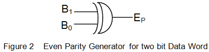
Parity Generator | Electrical4U from www.electrical4u.com O first, analyze and determine the possible of input lines combination in the circuit. The errors can be detected. The circuit diagram of odd parity generator is shown in the following figure. Cyclic redundancy check (crc) and checksum are other error detection methods. Build the truth table for all 16 possible states of the four bits and note the desired output (a 1 when the bits don't add up to odd parity.) the most naive implantation will have and and not gates for each possible state that needs to produce a o. But the receiver cannot correct the error because of ambiguity how does the circuit computes the crc code for a message: In the even parity method, the value of the bit is chosen so that the total number of 1s in the transmitted signal, including the parity. Each time an arrow is p if the nrz bit is 0 (1), it will be 0 (1) for two clock2 periods.
P a parity checker for serial sequences must be remembered by the circuit and set up states accordingly 5.
Nrz data x converter z manchester. In the case of odd parity, the situation is reversed. Also, watch motion detector circuit. Question 4 odd/even parity detector consider a logic circuit that counts the number of ones in a bit serial input stream. The various error detection techniques are. And if the sum of bits with a value of 1 is even, the parity bit value is set to 1, making the total count of 1's in the set an odd number. An odd parity checking or an even parity checking has to be agreed between a transmitter and receiver. So, the resultant word (data) contains 4 bits, which will be received as. The parity generator is a combination circuit at the transmitter, it takes an original message as input and generates the parity bit for that. This paper presents three bit odd parity generator and detector circuits based on low power adiabatic logic technique. Both have an even output bit and an odd output bit, which is set to a high level if the corresponding parity is detected. A parity bit, or check bit, is a bit added to a string of binary code. But the receiver cannot correct the error because of ambiguity how does the circuit computes the crc code for a message:
Cyclic redundancy check (crc) and checksum are other error detection methods. Present the first bit of the message. There are two parity methods, even and odd. Write its boolean expression without using the xor operator (). Reset all the dffs (memory elements) to zero.
Step by Step Method to Design a Combinational Circuit ... from i2.wp.com P a parity checker for serial sequences must be remembered by the circuit and set up states accordingly 5. But the receiver cannot correct the error because of ambiguity how does the circuit computes the crc code for a message: The circuit diagram of odd parity generator is shown in the following figure. We can embed circuits for 2, 3 and 4 bits and also show the karnaugh map method for higher bits. Also, they have an enable input. Even parity generator and odd parity generator, combinational circuit in digital electronics. There are two parity methods, even and odd. A parity bit is an extra bit included in binary message to make total number of 1's either odd or even.
The various error detection techniques are.
Steps to design the circuit using the circuit construction algorithm: Parity check is responsible for an accurate data transmission between the nodes during communication. Question 4 odd/even parity detector consider a logic circuit that counts the number of ones in a bit serial input stream. So, the resultant word (data) contains 4 bits, which will be received as. 4bit odd parity using 8x1 multiplexer. Also, watch motion detector circuit. Reset all the dffs (memory elements) to zero. Both have an even output bit and an odd output bit, which is set to a high level if the corresponding parity is detected. The errors can be detected. The circuit diagram of odd parity generator is shown in the following figure. We can embed circuits for 2, 3 and 4 bits and also show the karnaugh map method for higher bits. Single parity check uses a parity bit to perform error detection. Parity bits are a simple form of error detecting code.
Related : 4 Bit Odd Parity Detector Circuit : Build the truth table for all 16 possible states of the four bits and note the desired output (a 1 when the bits don't add up to odd parity.) the most naive implantation will have and and not gates for each possible state that needs to produce a o..